Scan to Connect & Connection Troubleshooting
1. Scan the QR code to connect
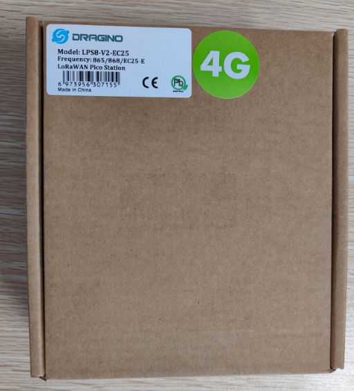
The outside of Dragino's device packaging has device information and a QR code with IMEI information printed on it.

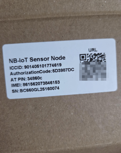
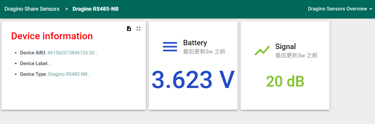
The inside of Dragino's device packaging has device information and a code printed on it. Scanning the code will redirect you to the default dashboard containing the device information.
The inside of Dragino’s device packaging contains the device information and a printed QR code. Scanning this code redirects you to the default dashboard displaying the device details. If you scan the code using the Dragino mobile app, the device will be automatically added to the account currently logged into the app. Please note that once the device is bound in this way, you will no longer be able to access the default dashboard, nor can the device be bound again.
Dragino mobile app download link: Where can i download the mobile APP?
2. How to connect the device/update the firmware
Here list the models that support BLE and the method to activate BLE function.
| Models | BLE Activate Method | Comments |
|---|---|---|
| All models with -LB, -LS , -NB, -NS, -CB, -CS suffix | Device is battery power type and BLE will be only activate on below case: * Press button to send an uplink * Press button to active device. * Device Power on or reset. If there is no activity connection on BLE in 60 seconds, sensor will shut down BLE module to enter low power mode. |
Below hardware use LoRaST v4 module. They supports UART Access for AT Command and Firmware Upgrade.
| Models | Mother Board | UART for AT Commands | UART for Upgrade Firmware |
|---|---|---|---|
| PS-LB, PS-LB-NA, SDI12-LB | SIB | Instruction | Instruction |
| SN50v3, S31-LB, S31B-LB,D20-LB.D20S-LB, D21-LB, D22-LB , SW3L-LB | SN50v3 | Instruction | Instruction |
| LHT65N | LHT65N | ||
| RS485-LB, SE01-LB, SPH01-LB, LMS01-LB, LDS12-LB, LDS40-LB, DDS75-LB, DDS45-LB, DDS04-LB, DDS20-LB, MDS120-LB, MDS200-LB, WSC2-LB, LDS25-LB | RS485-BL | Instruction | Instruction |
Below hardware use NB ST -BC660K-GL module. They support UART Access for AT Command and Firmware Upgrade.
| Models | Mother Board | UART Wiring | UART for Upgrade Firmware |
|---|---|---|---|
| PS-NB, PS-NB-NA, SDI12-NB | SIB | Instruction | Instruction |
| SN50v3-NB, S31-NB, S31B-NB, D20-NB. D20S-NB, D21-NB, D22-NB, DS03A-NB | SN50v3 | Instruction | Instruction |
| RS485-NB, SE01-NB, SPH01-NB, LMS01-NB, LDS12-NB, LDS40-NB, DDS75-NB, DDS45-NB, DDS04-NB, DDS20-NB, MDS120-NB, MDS200-NB, WSC2-NB | RS485-BL | Instruction | Instruction |
3. Signal Strength:99
3.1 What is Signal Strenght?
NB-IoT module can't connect to NB-IoT Network and Keep Showing Signal Strenght:99. Below is an example output:

Signal Strength is same as AT+CSQ command output. When you run AT+CSQ and NB-IoT module return AT+CSQ=99,99. It means NB-IoT Sensor doesn't attached to the NB-IoT network. If attached to network, the first 99 should be 2~31.
Below is the definition for the AT+CSQ
3.2 What to check?
Check whether module detect the SIM card?
You can see if the output shows the IMSI number. If NB-IoT module detects SIM card successful, There will be a IMSI number shown, this is from the SIM card. If SIM card not detect, please check:
- If SIM card is placed in correct direction.
- Make sure there is power off / power on after insert SIM card.
3.3 Whether you use a NB-IoT SIM card that the module supports
- Make sure the SIM card you use is a NB-IoT SIM card. It is different from normal SIM card we use for mobile.
- If you use a NB-IoT SIM card, check whether the Frequency Band of this operator are in the support list of the NB-IoT Sensor.
3.4 Whether the antenna connection is good
See the connection of Antenna Path is loose.

3.5 Check Software Settings
In the NB-IoT Sensor which power by battery. The sensor will try to connect to NB-IoT in a specify time (For example 5 minutes), if sensor is not able to attach network in 5 minutes. Sensor will stop retry and put the NB-IoT module in sleep mode to save battery life. So in the case that attaching network needs more time than 5 minutes, it will cause module hard to attach NB-IoT network. There are two solution to solve this.
3.5.1 Extend attach time
User can use AT Command to extend network acquisition time.For example AT+CSQTIME=10 will extend the network acquisition time to 10 minutes.
3.5.2 Lock Frequency Band
NB-IoT module by default support multi-bands, and it will try to use these bands to attached network one by one. User can lock the frequency band to the SIM card band to speed up the process.
See how to lock frequency band.
4. The address cannot be parsed/incorrectly filled in
If the signal is normal but the connection still fails, it is reasonable to suspect that the address resolution is faulty.
The default configuration is as follows:
- Set to use ThingsEye UDP server: AT+SERVADDR=thingseye.io,11560
- Set to use ThingsEye ChirpStack server: AT+SERVADDR=lns1.thingseye.io,11560
- Use UDP Uplink & Json protocol: AT+PRO=2,5
If the NB device cannot resolve the domain name, it will directly use the IP address
- Set to use ThingsEye UDP server: AT+SERVADDR=47.251.43.52,11560
- Set to use ThingsEye ChirpStack server: AT+SERVADDR=47.254.40.251,11560
- Use UDP Uplink & Json protocol: AT+PRO=2,5
If you don't know the domain name IP, you can enter the command AT+QNDS to resolve the domain name when it is not working (this process may take a long time).
Example:
AT+QDNS=0,www.baidu.com
OK
+QDNS:111.13.100.91
5. How to configure different APN
First:AT+CGDCONT Define a PDP Context
The write command specifies PDP context parameter values for a PDP context identified by <cid>, and the (local) context identification parameter. It also allows the TE to specify whether security protected transmission of ESM information is requested, because the PCO can include information that requires ciphering. There can be other reasons for the UE to use security protected transmission of ESM information, e.g. if the UE needs to transfer an APN. The number of PDP contexts that may be in a defined state at the same time is given by the range returned by the test command. Please refer to Chapter 6 for possible <err> values.
For EPS, the PDN connection and its associated EPS default bearer is identified herewith.
A special form of the write command, AT+CGDCONT=<cid> causes the values for context number <cid> to become undefined.
If the initial PDP context is supported, the context with <cid>=0 is automatically defined at startup, the parameters for <cid>=0 can be modified with AT+CGDCONT. If the initial PDP context is supported, AT+CGDCONT=0 resets context number 0 to its particular default settings.
The read command returns the current settings for each defined context.
The test command returns values supported as compound values. If the UE supports several PDP types, the parameter value ranges for each <PDP_type> are returned on a separate line.

COMMAND:

Parameter
Example:
AT+CGDCONT=? +CGDCONT: (0-10),("IP","NONIP","IPV6","IPV4V6"),,,(0),(0),,,,,(0,1) OK AT+CGDCONT=1,"IP","HUAWEI.COM" OK AT+CGDCONT? +CGDCONT:0,"IPV4V6",,,0,0,,,,,0 +CGDCONT:1,"IP","HUAWEI.COM",,0,0,,,,,0 OK Users can directly use the AT command to set APN.
AT+APN=
<APN>
Quit AT Command
Feature: Quit AT Command mode, so user needs to input the password again before using AT Commands.
AT Command: AT+DISAT
| Command Example | Function | Response |
|---|---|---|
| AT+DISAT | Quit AT Commands mode | OK |
6. Traffic Statistics
Configure NB-IoT End Node to send data packets every 10 minutes, and statistics the daily usage of traffic for NB-IoT End Node.
| Connection mode | Data transmission interval (minutes) | Total packet | Total traffic consumption (MB/day) | Average traffic consumption per packet (MB) |
|---|---|---|---|---|
| MQTT | 10 | 136 | 0.23 | 0.00169 |
| UDP | 10 | 144 | 0.11 | 0.0008 |